Index:


Projects

This section has info on (some) of the random projects that I am working on…

I am working on a bunch of projects that I haven’t gotten around to documenting yet, but hopefully will soon.


Here is a partial list – some of these have some preliminary info, but no full write-up yet:

  • Home made CNC stepper motor based milling machine.
  • FPGA based password cracker.
  • Lightwave Electronics 25W green Nd:YAD diode laser.
  • OS X Iris Recognition security module.
  • OS X Fingerprint reader toolkit.
  • E-passport hacking.
  • Hacking scratch off lottery tickets using optical means.
  • Fixing Bose Sleepbuds refusing to charge problem.

    I have a pair of Bose Sleepbuds, which I exclusively use when traveling.

    They are good at blocking out noise from hotel A/C units, elevators, people wandering up and down the hallways while having loud conversations, etc. Unfortunately they have a well known issue – the sleepbuds themselves get charged by a special charging case, and the Battery Management System (BMS) won’t charge the battery in the case if it falls below a certain voltage.

    This means that if you don’t regularly charge the case (for example because you are not traveling because of Covid), the battery will drop below this voltage, and the BMS won’t wake up and charge the battery.

    This short writeup explains how to make them work again:

    Step 1: Peel the bottom rubber cover off


    This is simply held on with some double-sided adhesive. Warming it up will make it come off easier and allow you to more cleanly reuse the adhesive. Otherwise, just pull it and use new adhesive (or just leave it off and save a gram or two in your luggage!). Next, remove the really small torx (or security torx, I cannot remember which) screws and pop the back off.  

    Step 2: The root problem is that the BMS won’t charge the battery once it falls below a certain voltage, so all we need to do is momentarily raise the voltage about that point. 

    Simply momentarily apply 3V across the battery – I used TP1 and Ground, and will soon update this post with better pictures showing where. Note that the battery implies that it is  7V (7V 225mAh), but this is not the case, it is actually a standard 3.7V cell.

    This at least got it working so that I could use them on a trip, but I’m planning on sometime extending these points so that thay are externally accessible, or repurposing the reset button to bridge from the USB input to the battery so that I can kick-start it with a paperclip.  

  • Westover P5000 scope: Making an awful device marginally less awful

    Westover P5000 scope: Making an awful device marginally less awful

    I have a Westover Scientific P5000 fiber scope. I like the device itself, but the last time ThermoFisher released software for it was 2010, and it required Windows® XP or Vista Operating System (or, with much fighting, possibly Windows 2000). Based on the price of the device this is annoying, but ThermoFisher seems to often abandon their products.

    Anyway, I haven’t been able to find a nicer fiber-scope, and it was really annoying me that I could no longer use this one – it’s basically just a camera and some funny optics, and so I decided to try and fix it (the other alternative was tidying my office,  and that sounded like less fun…) I ended up swapping out the sensor and electronics for a cheap webcam module. Here is my build journey in case anyone else wants to do the same…

    IMG 7006  IMG 6980


    It uses Torx screws (for some reason the optics module uses security Torx).

    Inside is an optics package, a small sensor board, and a larger video to USB board. Connecting the two boards together is a flat-flex cable. It uses the same cable that the Raspberry Pi camera module uses; I was initially excited, hoping that this might be a standard pinout, and I could just slap a Raspberry Pi in intead, but no such luck. I pulled out the electronics, and then took apart a Logitech webcam, hoping that I could replace the sensor module with the guts from the Logitech – this almost worked, but like the fiber scope the webcam has two boards, and the connector on the sensor board faces “forward”, which would get in the way of the optics package. The connector seems to be 0.2mm pitch, and so it wasn’t really fesiable to desolder it and run nrew traces or move it to the back of the board.

    Instead I found a small USB webcam module – ELP megapixel Super Mini 720p USB Camera Module with 120degree Lens and replaced the sensor and electronics with this. Unfortunatly it did require carving a way a little bit of the casing with a Dremel tool, and I got a  bit impatient and cut all the way through, but it still looks and works well.


    Picture of the optics module. It is basically a microscope, and a blue illumination LED, with a 45-degree beamsplitter to allow the LED to illuminate the front surface of the fiber. The LED sits in the front, and seems to be powered by ~3.3V

    IMG 6979 


    The webcam module – this was $29USD from Amazon. The webcam module I chose has a 120 degree field of view, but this isn’t really important, because I remove all of the optics and am only using the sensor. The module itself on a (I’m guessing?) standard size PCB, but has “slots” to allow the outer part of the board to be removed.

    IMG 6984

    Finding a handy 3.3V source to power the LED. There is a handly looking set of contacts (lower left), unfortunatly they are GND and USB 5V. Probing around I found a handy 3.3V supply

    IMG 6986  IMG 6985

    IMG 6993

    Snipping off the “break away” outer board. I’m assuming that both the outside and inside boards are a standard size

    IMG 6988 

    Removing the original sensor mount from the sensor board. The adapter screws into the back of the optics package, and protects to sensor. I used a heat gun to heat up the mounting glue, and popped it off. After removing the lens assembly from the new webcam module, it slides nicely into this mount, and a dab of hotglue holds it nicely in position. The adapter has some slots to allow fine-tuning of the sensor position.

    IMG 6989

    In order to make this particular webcam module fit, I had to trim the case slightly with a Dremel tool – I’m sure I could have found a smaller camera module (I considered using an endoscope, but that seemed like more trouble than I wanted to deal with). I got somewhat impatient / over-enthusiastic, and ground through the edge of the case, but a smaller board or a bit more patience should solve this. I also added some pennies to give the unit a slightly nicer heft. 

    IMG 7001

    IMG 7006 IMG 7007

    As it now contains a standard webcam, this now works perfectly on Linux and Apple macOS X devices without any sort of drivers

    IMG 6980


  • Fixing a Joule Sous Vide motor / seal

    Fixing a Joule Sous Vide motor / seal

    We have a Joule sous vide which recently developed an issue – the motor which drives the impeller started sounding like it was struggling, and then one day it just stopped in mid cook. 

    Joule

    We do not have particularly hard water, but I tried the standard “run it in a vinegar / water solution” – this made a tiny improvement, but not enough to make a useful difference. I looked some online, but wasn’t able to find any repair instructions – there were a number of posts showing that bits are glued in, and so it cannot be disassembled easily. 

     Anyway, I was not happy throwing it away, so I decided to try fix it – this worked for me, it may or may not work for you as well. Obviously, do this at your own risk, I take no responsibility for, well, anything…

     Firstly, get some thin silicon oil – I use “Super Lube 56104 Silicone Oil 100 CST” – you are looking for something thin, silicone grease won’t work for this.


    Flip the Joule over, and use some tape to block off the water outlet – I used Kapton tape because it was handy, and knew that the adhesive would survive the oil.


    Remove the impeller – it has a small hole in it specifically for using a fork to pop the impeller off.

    Image of impeller

    Squirt a little bit of the oil in (another advantage of Kapton tape is that you can see the liquid level) – I filled it to around 1/2 way up the water exit hole. Now, leave it to sit for a few hours. Every now and then wiggle the shaft – it is remarkably stiff, and so can take a fair bit of force, but don’t push too hard or you might bend it. Basically, you want to try get some of the oil to slide down the shaft so it lubricates the seal.

    After a few hours I was getting impatient, and so I bent a paperclip into a small hook, chucked it in a drill, and used this to spin the impeller for a while. After I’d done this the shaft was noticeably easier to turn, so I flipped it over and tested it — and it now runs like new…


  • Improving the Airconsole LE

    Improving the Airconsole LE

    I’ve long been a fan of the Airconsole portable Wifi / Bluetooth to Serial devices. They always work well, they connect to anything, and it is really nice to be able to have a console connection without having to ballanve your laptop on the edge of a rack / router / whatever.


    They recently released the Airconsole LE – a portable, long battery life BLE based unit. Unfortunatly it is much larger than it needs to be – and I mainly carry a console server for emergency use. If it takes up too much space in my bag, I won’t carry it, and then it is of no use.

    Don’t get me wrong – Get Console / Airconsole are still awesome, this particular prodict of theirs could just be even better!

    IMG 5609


    The huge majority of this size comes from the comically large RJ45 connector – I get that they built it ruggedly so that it would survive being knocked about / used as a handle for carrying switches around, etc, but this is taking it a bit far!!

    IMG 5610


    I ended up disassembling it and using a dremel tool to cut away the majority of the strain releif on the back of the connector.

    IMG 5612


    I then printed a 3D case out of glow-in-the-dark fillament. Partly this was because this was what was already loaded in my printer, but also so that it might be a little easier to find in the depths of my bag. It is now almost 1/2 as long, and much thiner and narrower as well (the new case slides competely inside the old one 🙂


    IMG 5613

    IMG 5614


  • Repairing a Haas Rotary Table controller

    Repairing a Haas Rotary Table controller

    A friend of mine has a Haas 4th axis / rotary table, which he wants to drive from a Matsuura CNC mill. Unfortunately, no matter parameters and options what we tried we were unable to talk to the HAAS controller over the RS-232 port. 

    This is a fairly common device, and so I figured I’d provide some information on repairing it.

    I recently ran into an issue with a “Datum PRS-50 Cesium Beam Primary Reference Source” which I couldn’t talk to using any of my USB to Serial converters – after some debugging I figured out that this was because all the USB->Serial devices I tried seem to only output 0V to +8-10V, while the spec calls for -5-25V to  +5-25V. This works for “modern” devices, but not for some older ones, and so needed to use a machine with a “real” serial port for the PRS-50 (as a side note, if anyone knows of a USB to RS-232 which actually does full voltages, please let me know!). I figured that this might be the same issue with the HAAS controller, and so tried with a desktop with a known good serial port, but this didn’t help, and so I decided to dig a bit deeper.

    Being made in 1995, this Haas controller is all through-hole DIP construction.


    The controller has 2 serial ports, one Upstream (to the CNC machine / PC), and one Downstream (for daisy-chaining controllers). I opened it and first checked the connectivity from the serial port to all of the pins on the ribbon cable, and then to the rear of the board — the IDF connector was slightly loose but seemed to make good enough connectivity. I then ran it on a workbench and hooked it up to an oscilloscope and traced the serial signal. The input goes through an MC1489P Quad Line EIA-232D Receivers, which then hands the signal off to an NEC PD71051 Serial Control Unit (which receives serial data streams and converts them into parallel data characters) which finally hands this to a Z80 series CPU. Return traffic (which only seems to come in response to “xP” commands) goes through the PD71051 and then an MC1488P Quad Line EIA-232D Driver

    Tracing the serial signal showed that it wasn’t arriving at the PD71051. The obvious culprit here is the MC1489, and so I desoldered this and the MC1488, installed sockets (so future replacements are easier) and installed new ones.

    Removed MC1489  Removed chips 

    Fixed

    Removed both Socketed 

     After testing this on the workbench and checking the signal with a scope I could now see the serial signal arriving at the MC1489P, but didn’t bother hooking up a protocol analyzer to check the output – instead, I just sent an XP command, got back “01” as the response, buttoned it al up and tested it — and now it works.


  • Replacing a Symmetricom ND-4 processor with a Raspberry Pi

    Replacing a Symmetricom ND-4 processor with a Raspberry Pi

    I’ve had a broken Symmetricom ND-4 wall mount NTP clock display sitting around for ages. For some reason, this turned into one of those projects where I decided I really wanted to get it working. It was such a simple device that it seemed stupid that I couldn’t fix it.  


    Poking around showed that the power supply seemed fine, but the Realtek RTL8019AS Ethernet chip was obviously faulty (AKA, it got hot!).

    I tried replacing it, first with a pull from a different board, and then with a new one (I have a hot-air rework station and reflow oven). This didn’t fix it, and some more research / probing of the (Rabbit 2000) processor showed that there were more issues – the UART was obviously trying to send something, but the baud-rate was nothing sensible, etc.

    Processor board

    Eventually, I gave up trying to repair the processor board and it just sat in the corner of my workshop, gathering dust. But it kept bugging me, and so I decided to give it another whirl.

    The display itself is a 7 segment LED driven by a MAX7219 (“Serially Interfaced, 8-Digit, LED Display Driver”) with 4″ high digits. This is a very common LED display driver, and there is a nice Python library for driving it, so….

     
    I ripped out the processor board, and replaced it with a Raspberry Pi Zero W. The ND-4 power supply already has a 5V rail, suitable for the Pi, and the MAX7219 is easily driven over the Pi SPI bus.
     
    The wiring is as follows:
    ND-4 MAX7219 Function Pi Pin
    VCC   VCC 2
    GND   GND 6
    PA0 CLK SPI CLK(11) 23
    PA1 LOAD/CS SPI CE0(8) 24
    PA2 DIN MOSI(10) 19

    The Pi speaks NTP to get the correct time and uses the luma.led_matrix library to drive the display. 

    Code is here: https://github.com/wkumari/symmetricom-nd4-python


    Driver board Pi connection Running Mounted Pi


  • Making a CTEK to Ferrari battery tender adaptor cable.

    Making a CTEK to Ferrari battery tender adaptor cable.

    Ferraris are notorious for having high idle / standby current draw, and they end up with all sorts of weird and hard to troubleshoot issues if their battery voltage drops too low. They also often have radios and similar which need (expensive) reset codes, or alarm systems that decide to forget their fobs. They are also often stored for the winter (being high power rear wheel drive cars, usually with summer tires, driving them in the winter is often, um, exciting!).

    This makes storing them on a battery charger or tender critical – unfortunately, many people have either lost their Ferrari branded charger, or never had one. The charger which Ferrari supplies with most of their vehicles is the lowest end CTEK charger, with a special connector – this connector plugs into a special jack (usually in the trunk or passenger footwell), which disables the starter motor (to prevent the embarrassing “driving down the road with the charger still connected” issue :-)) – more info on the charger connector.

    f430-charger-connected-icon   Ferrari-599-charger-connected-icon


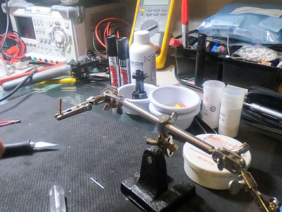
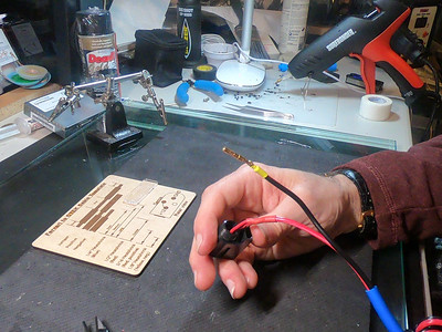
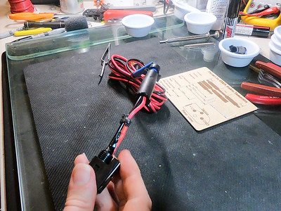
    The following contains some information on how I make these cables – I make other cables for mission-critical purposes, and so I’ve gotten into the habit of seriously over-engineering cables – while I could just slap the proprietary Ferrari connector on the end of the CTEK leads, instead I solder and crimp the contacts, moisture-proof the connectors (by blocking the unused pin and the rear with foam, and then fill the body with hot-glue), install 4 layers of heat-shrink, etc.

    Each one takes me multiple hours to make, so here are instructions/picture in case you’d like to make your own. 

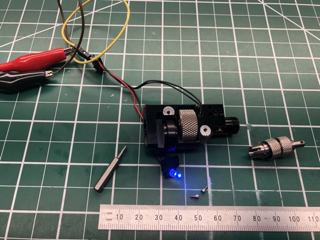
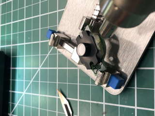
    To improve quality I created a template on a laser cutter:

    Cable template 1    Cable Template 2

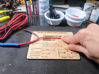
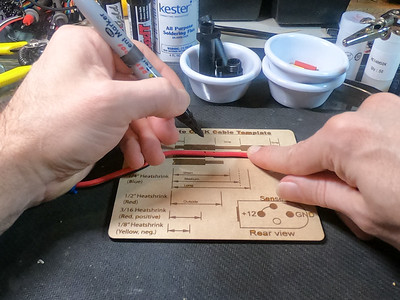
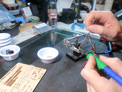
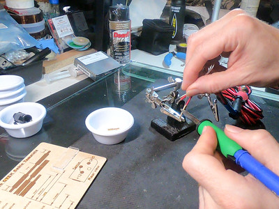
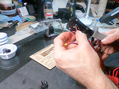
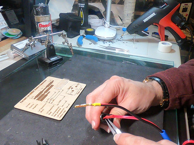
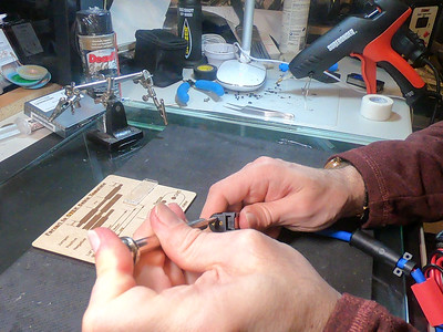
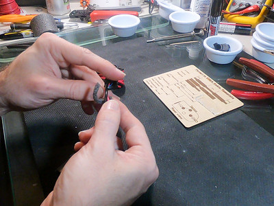
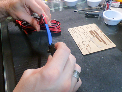
    To improve the connector strength (and decrease resistance), I apply flux to the contact, then fill with solder, before inserting the wire (and backfilling with solder)

    Contact Filling contact with solderBackfill with solder

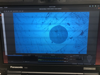
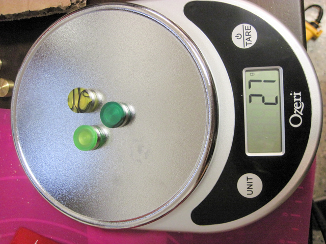
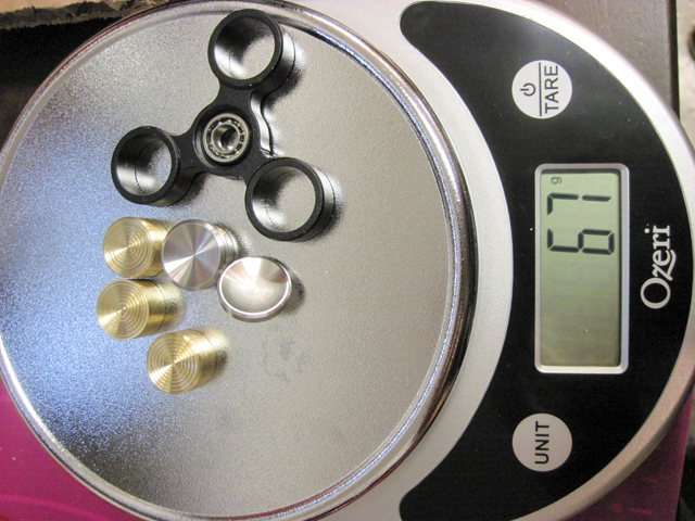
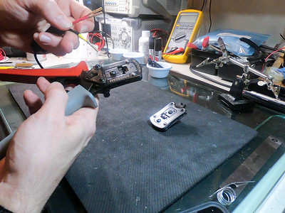
    It is really important to use the correct crimping tool for these contacts – I have tested the pullout strength using just solder, solder and an incorrect crimp, and solder and the correct crimp. The correct crimp makes a huge difference. The solder and (correct) crimp also provided the lowest electrical resistance by far (tested using the four-wire Kelvin technique). These contacts really need the S16RCM1450 or S16RCM16 crimp heads (available from DigiKey or Mouser) and Souriau crimp handles – the set is somewhat expensive (at ~$400), but the quality of the crimp is well worth it.

    Crimping the contacts Crimping the contacts

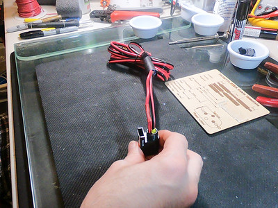
    To help with moisture protection, I cut and insert a small piece of foam into the unused contact spot

    Small piece of foam Inserting foam Inserted foam

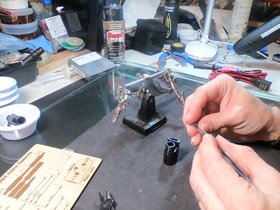
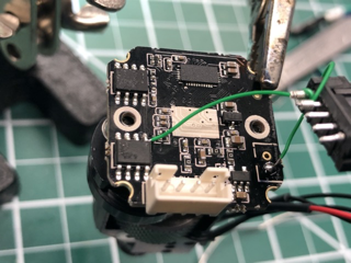
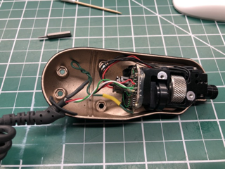
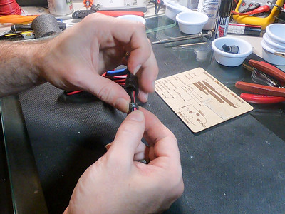
    And then insert the contacts

    Contacts1 Contacts2 Contacts3

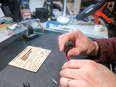
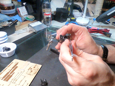
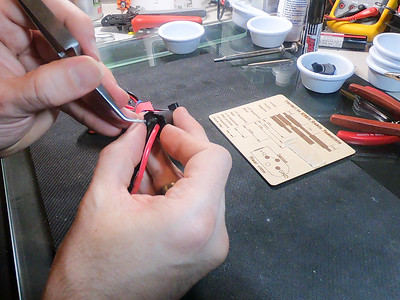
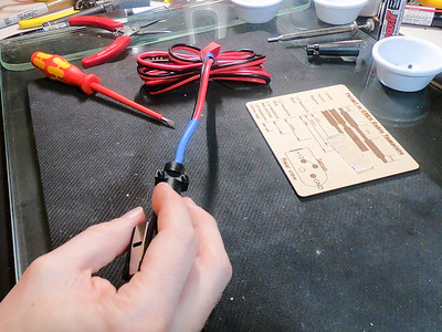
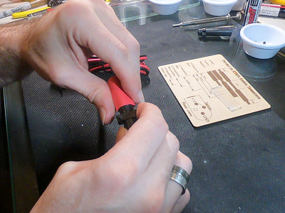
    Getting them fully inserted is sometimes tricky, and so I strip a bit extra from the negative lead and then tin and heat-shink it just behind the connector – if I don’t do this, the insulation around the wire stops it seating properly. I then use a Molex-tyle pin remover to check that each pin is securely clipped in,

    Negative heat shrink Pin setting Pin check

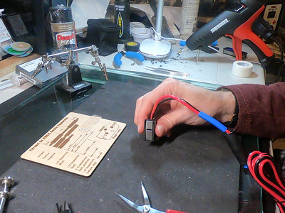
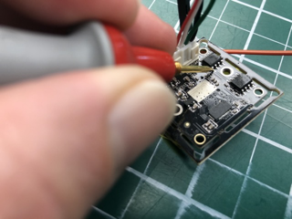
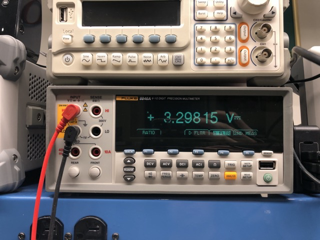
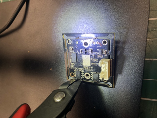
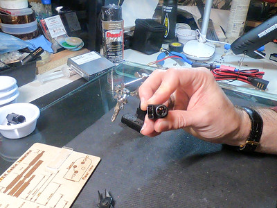
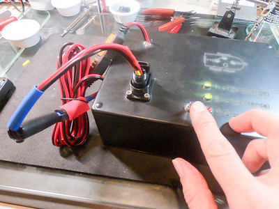
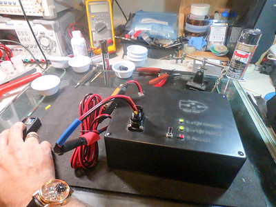
    Once the pins are all inserted I do an initial test.

    Test for ground short Test for continuity Test

    It then gets a good glob of waterproofing / strain-relief sealant on the contacts / wiring

    Sealant1 Sealant2 Sealant 

    Some more foam gets wrapped around the wires towards where the end of the strain relief boot goes, and (temporarily) held in place with some more sealant

    Rear sealant Rear sealant2 Rear sealant 3 

    Rear sealant 4 Rear sealant

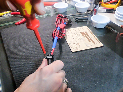
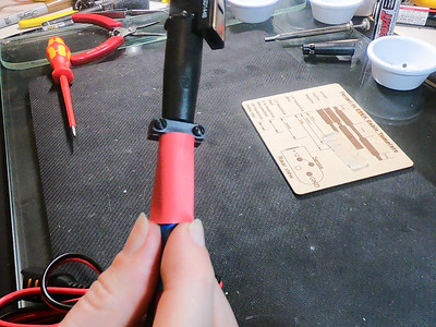
    And now for the tricky bit. I add a bunch more sealant to the strain-relief boot, and then quickly screw it all together, before the sealant has a chance to set.

    Closing1 Closing2 Closing3 

    And then screw on the strain-relief clamp

    StrainClamp1 StrinClamp2

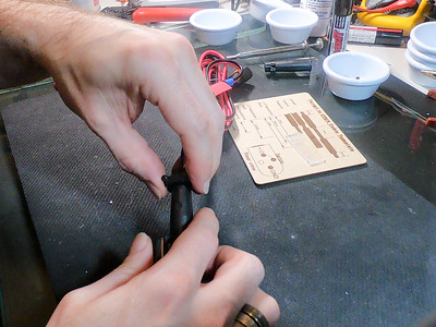
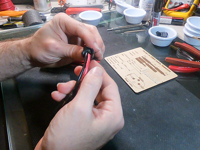
    Actually, this bit might be the trickiest, or at least the one with the most chance of cursing; right at the beginning of the process, I’ve (hopefully!) remembered to put on all of the extra water-proofing heatshrink.

    Heatshrink Heatshrink2 

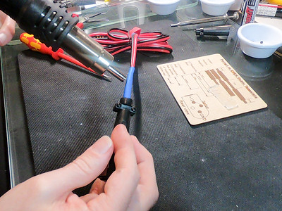
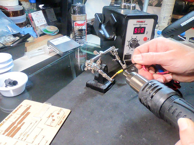
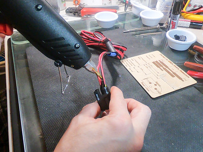
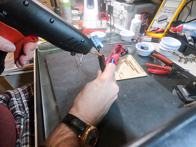
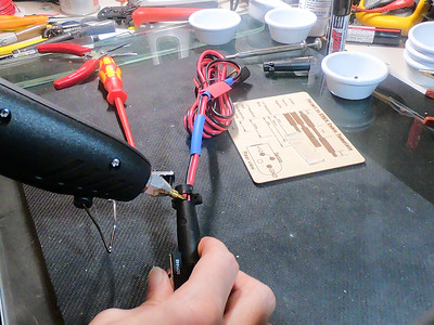
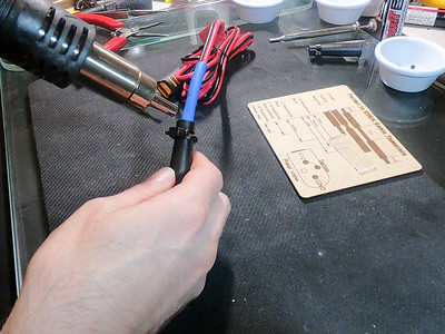
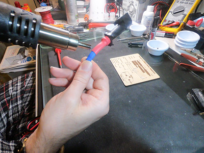
    It gets (usually) 3 layers of heatshrink to build it up

    Heatshrink Heatshrink4

    And them some final sealant in the back of the boot

    Boot seal1 Boot seal 2 Boot seal 3

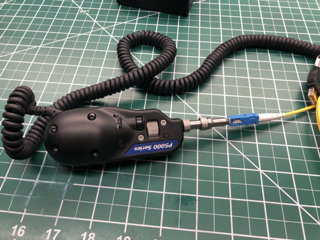
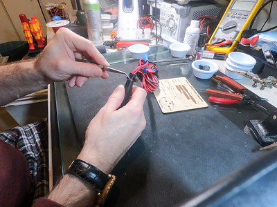
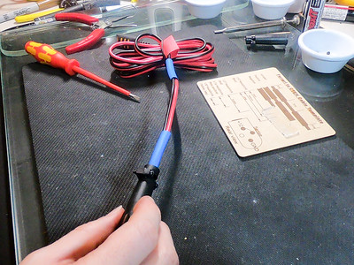
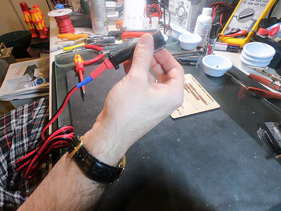
    And then a final layer of heatshrink over all of this to finalize the seal.

    FinalSeal1 FinalSeal2 FinalSeal3 FinalSeal4

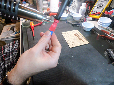
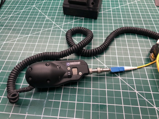
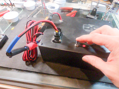
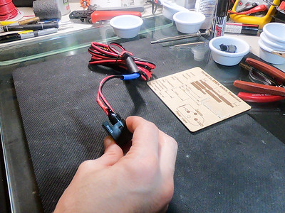
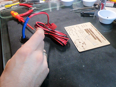
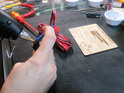
    And the cable is all done, just needs a final test and label
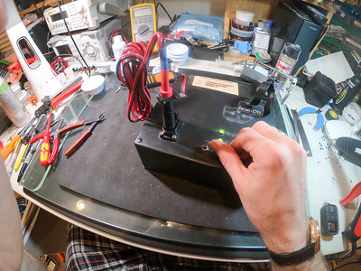
    Final assembly Final test

    Done

    Done1 Older-bagged


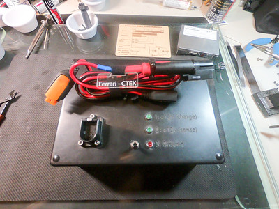
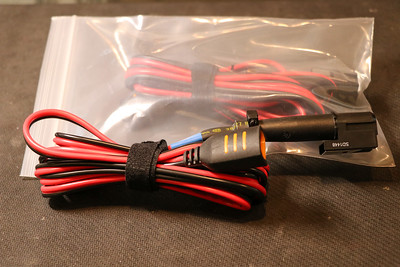
    Photo album: http://photos.kumari.net/Projects/CTEK-Ferrari-Cable-Instructions/ and older page with more details: https://www.kumari.net/index.php/cars/ferrari-battery-charger-cable


  • Improving a fidget spinner

    Improving a fidget spinner

    I recently attended ICANN 59 in Johannesburg, South Africa.
    While there I picked up a fidget spinner. It worked reasonably well, but it was not very well balanced and so shook somewhat while spinning. This bugged me (probably more than it should have!), and so I decided to do something about it.

    IMG 0258

    If I held it vertically and gave it a quick spin, it would fairly much always stop with the light green arm point up. This means that the other two arms needed some material removed. I estimated how much would ned to be removed by adding hot-glue to the lighter arm to balance that, and then remove roughtly half that from each arm.

    IMG 0259

    I couldn’t figure out how the weights were held in the arms (it looked like a press-fit, but was very tight) and so I decided to try and mill some material off the outside of the arm. After removing some material on my little Sherline mill, it became clear that this wasn’t going to provide nearly enough benefit (the body of the spinner seems to be aluminum, and the weights seemed much heavier) and so I decided that I needed to get the counterweights themselves out. I heated the arms up with a heat gun and managed to press the weights out.

    IMG 0260

    Unfortunately, I didn’t have my higher precision scale handy, but even using a lower precision one it was clear that the weights were different.

    I put each weight in a Sherline lathe, removed bits of material and kept checking to see if this had fixed it. 

    IMG 0262

    IMG 0261

    After removing much more material than I would have expected, I got it nicely balanced.

    IMG 0263


    Of course, if something is worth doing, it’s worth over-doing, and so I decided to replace all of the weights with larger, brass ones (I also enjoy turning brass). So, I turned down some brass rod to (slightly over) dimension, parted it off, and made small cuts to balance them.

    I then turned small decorative cuts into the face, which also happen to improve the feel. The new weights are significantly heavier than the old – 41g versus 27g, heading to noticeably longer spin times.

    IMG 0266

    IMG 0267

    IMG 0268

    Finally, the bearing felt somewhat rough, so I cleaned it in an ultrasonic cleaner, with some L & R #566 Ultrasonic Non-Ammoniated Watch Cleaning Solution, rinsed it in L & R Ultrasonic Watch Rinsing Solution and oiled the bearings with some Moebius 8000/4 oil. The Moebius turned out to be somewhat too thin, so I replaced it with

    IMG 0270

    IMG 0271

    IMG 0273

    It is now much improved. All of this was way more work than it justified, but, hey, that’s not the point!

  • Atomic Clocks / NTP

    I’ve always been interested in high accuracy time, and measuring things really exactly.

    IMG 4537 IMG 4686 IMG 4599  

    I recently decided that I wanted to have an accurate source of time at home, and so, obviously, I needed some cesium clocks, some rubidium oscillators and some GPS timing sources. This was for my home use, and I couldn’t justify spending new prices, so I decided to get some used gear – this page/section has some info on refurbishing and upgrading timing devices.

    I wanted to be able to supply devices with NTP time, and also to be able to improve the accuracy by adding an atomic clock. I also figured that I’d like to to be able to support IPv6, and so I ended up deciding on a Symmetricom SyncServer S250. This device has 3 Ethernet ports for NTP, 10Mhz input (so I can add higher stability sources) and outputs (to monitor the stability) and 1PPS in and out. They are also relatively cheap, going for ~$1,200 on eBay. I found one which had damaged rack ears, and the seller didn’t know much about it for somewhat less. Unfortunately it didn’t come with the Rubidium oscillator option (which I figured I could add later), nor the antenna.

    The SyncServer gets its time from GPS satellites. These provide the perfect source for timing; GPS positioning relies on the receiver knowing the exact time, so the GPS satellites have very high accuracy clocks and are kept true.

    When the GPS signal is locked, the S250 is accurate to nanoseconds, but if the GPS signal is lost (for example during a storm, if the GPS signal is turned off, if the satellites all die, etc) the device goes into “freewheeling” mode and needs to track time on its own. For this reason, the S250 comes with a built in temperature compensated crystal oscillator (TCXO) that keeps the server accurate to nanoseconds when the GPS is locked, but when the signal is lost, it drifts up to 21 milliseconds per day (or about 1 second in 47 days). The rubidium oscillator option improves this to 6 microseconds per day (or one second in 4.5 years). I figured “in for a penny, in for a pound”, and so I decided that I wanted higher accuracy, and so needed a cesium primary refernce source – 3×10^-14, i.e. 0.00000000000002 Hz; this corresponds to a time measurement accuracy of 2 nanoseconds per day or one second in 1,400,000 years.

    The rubidium oscillator option (which improves holdover accuracy is 3 to 25 microseconds) is an internal unit, which connects to the main board. The SyncServer datasheet helpfully shows that this is a Symmetricom X72, which connects to a connector on the main board. These were widely used in various test gear, and so I found one on eBay for ~$250.

    I ended up reverse engineering the pinouts and made a custom interface board for it here. I’ll post pictures of the final, completed one, and pinouts later.


    Finding a good, cheap cesium oscillator was somewhat harder, but eventually, I found a Datum FTS 4060 Cesium Frequency Standard for sale at a nearby electronics surplus dealer. It powered up, but it wasn’t clear it would achive lock (they take a long time, especially after being in storage). The same dealer also had some Datum PRS-50 Cesium Primary Reference Source units (“The Datum PRS-50 Cesium Beam Primary Reference Source is a primary frequency reference with fully automatic operation via microprocessor control. It provides a Stratum 1 quality signal without the need of any external reference.”) – these are fairly common units and were used extensively in telecom central offices and cellular base stations. I ended up getting two of them.

    This page is still a work in progress. I’ll get hope to get around to publishing more details soon, until then there here are pictures here: http://photos.kumari.net/Projects/AtomicClocks

    The FTS 4060 ended up having some issues, which I’ve fixed – some details on its repair can be found here. [TODO: add this!]

    So far I’ve made one of the PRS-50’s work, but haven’t had a chance to look at the second – I think that it just needs a simple adjustment of the beam current, but simply haven’t had time to deal with it. Some more details here. [TODO]

  • Making a naked portafilter

    Making a naked portafilter

    A “naked” portafilter is one that has the bottom of the basket exposed. This:

    • allows the coffee to come out without hitting additional metal, and so is supposed to keep at a more consistant temperature.
    • preserves more of the crema  as the bubbles don’t burst when hitting the spigot.
    • allows you to better see the extraction process and so get better / more consistent  shots.
    • looks really cool!

    After spending a long time trying to find the perfect naked portafilter for our machine (Uniq Rumba) I ended up deciding to just make one. This is documented below.

    Start off by removing the plastic handle, metal bar handle and spigot. This can by difficult as they are dissimilar metals and so may have corroded together. I used a bunch of penetrating oil and then had to heat the spigot with a pencil torch.


    We want to remove the entire center section, so drill a bunch of close / overlapping holes. I did not have a centering bit, so I just placed them as close as possible to each other and then broke away the material between them with an old screwdriver bit (a bunch was too large). 

    To make this simpler / faster you can make a jig out of a piece of wood and a bolt though the spigot hole – this will allow you to drill, rotate, drill rotate and get all of the holes nicely lined up. I didn’t do this, but really should have!

    Now place the portafilter (without the metal handle!) on a lathe and machine away the excess material. I used a Central Machinery 7″ X 10″ Precision Mini Lathe. Something larger / more powerful would have made the process faster, but this worked ok. Running some fine sandpaper (on a dowel or similar) around the machined edge (while turning on the lathe) makes short work of tidying up the sharp edges, removing burrs and polishing the work.


    Now simply reasemble

    And test!