Index:


Cars

  • Ferrari 599GTB Fiorano

    Ferrari 599GTB Fiorano

    I recently traded in my Lamborghini Murcielago and replaced it with a Ferrari 599BGP Fiorano.

    IMG 5093 

    I’m really enjoying how much more civilized it is than the Murcielago. I can get in it and just drive, no worrying about what will happen if there is a raindrop, it is a coupe, and so is much quieter, the visibility is great, and because it is rear-wheel drive (not all wheel drive) you can have some more fun with it 🙂


    IMG 5095

    IMG 5108

    IMG 5115


    It is, of course, Rosso Corsa over tan.


  • Making a CTEK to Ferrari battery tender adaptor cable.

    Making a CTEK to Ferrari battery tender adaptor cable.

    Ferraris are notorious for having high idle / standby current draw, and they end up with all sorts of weird and hard to troubleshoot issues if their battery voltage drops too low. They also often have radios and similar which need (expensive) reset codes, or alarm systems that decide to forget their fobs. They are also often stored for the winter (being high power rear wheel drive cars, usually with summer tires, driving them in the winter is often, um, exciting!).

    This makes storing them on a battery charger or tender critical – unfortunately, many people have either lost their Ferrari branded charger, or never had one. The charger which Ferrari supplies with most of their vehicles is the lowest end CTEK charger, with a special connector – this connector plugs into a special jack (usually in the trunk or passenger footwell), which disables the starter motor (to prevent the embarrassing “driving down the road with the charger still connected” issue :-)) – more info on the charger connector.

    f430-charger-connected-icon   Ferrari-599-charger-connected-icon


    The following contains some information on how I make these cables – I make other cables for mission-critical purposes, and so I’ve gotten into the habit of seriously over-engineering cables – while I could just slap the proprietary Ferrari connector on the end of the CTEK leads, instead I solder and crimp the contacts, moisture-proof the connectors (by blocking the unused pin and the rear with foam, and then fill the body with hot-glue), install 4 layers of heat-shrink, etc.

    Each one takes me multiple hours to make, so here are instructions/picture in case you’d like to make your own. 

    To improve quality I created a template on a laser cutter:

    Cable template 1    Cable Template 2

    To improve the connector strength (and decrease resistance), I apply flux to the contact, then fill with solder, before inserting the wire (and backfilling with solder)

    Contact Filling contact with solderBackfill with solder

    It is really important to use the correct crimping tool for these contacts – I have tested the pullout strength using just solder, solder and an incorrect crimp, and solder and the correct crimp. The correct crimp makes a huge difference. The solder and (correct) crimp also provided the lowest electrical resistance by far (tested using the four-wire Kelvin technique). These contacts really need the S16RCM1450 or S16RCM16 crimp heads (available from DigiKey or Mouser) and Souriau crimp handles – the set is somewhat expensive (at ~$400), but the quality of the crimp is well worth it.

    Crimping the contacts Crimping the contacts

    To help with moisture protection, I cut and insert a small piece of foam into the unused contact spot

    Small piece of foam Inserting foam Inserted foam

    And then insert the contacts

    Contacts1 Contacts2 Contacts3

    Getting them fully inserted is sometimes tricky, and so I strip a bit extra from the negative lead and then tin and heat-shink it just behind the connector – if I don’t do this, the insulation around the wire stops it seating properly. I then use a Molex-tyle pin remover to check that each pin is securely clipped in,

    Negative heat shrink Pin setting Pin check

    Once the pins are all inserted I do an initial test.

    Test for ground short Test for continuity Test

    It then gets a good glob of waterproofing / strain-relief sealant on the contacts / wiring

    Sealant1 Sealant2 Sealant 

    Some more foam gets wrapped around the wires towards where the end of the strain relief boot goes, and (temporarily) held in place with some more sealant

    Rear sealant Rear sealant2 Rear sealant 3 

    Rear sealant 4 Rear sealant

    And now for the tricky bit. I add a bunch more sealant to the strain-relief boot, and then quickly screw it all together, before the sealant has a chance to set.

    Closing1 Closing2 Closing3 

    And then screw on the strain-relief clamp

    StrainClamp1 StrinClamp2

    Actually, this bit might be the trickiest, or at least the one with the most chance of cursing; right at the beginning of the process, I’ve (hopefully!) remembered to put on all of the extra water-proofing heatshrink.

    Heatshrink Heatshrink2 

    It gets (usually) 3 layers of heatshrink to build it up

    Heatshrink Heatshrink4

    And them some final sealant in the back of the boot

    Boot seal1 Boot seal 2 Boot seal 3

    And then a final layer of heatshrink over all of this to finalize the seal.

    FinalSeal1 FinalSeal2 FinalSeal3 FinalSeal4

    And the cable is all done, just needs a final test and label

    Final assembly Final test

    Done

    Done1 Older-bagged


    Photo album: http://photos.kumari.net/Projects/CTEK-Ferrari-Cable-Instructions/ and older page with more details: https://www.kumari.net/index.php/cars/ferrari-battery-charger-cable


  • Repainting Ferrari 599 Key

    Repainting Ferrari 599 Key

    Because of the snow and cold we’ve had this winter I wasn’t able to take my 599 out, or even spend some time in the gararge detailing it. 

    This made me antsy, and so I decided to finally take care of a minor issue that had been irritating me for a long time — the paint was shipping off the keyfob. This is a common issue, and usually starts right around the hole where the key attaches to the keyring.

    Here is a small writeup for others:

    Step 1: Disassemble key.

    The back (with the emblem) pops off easily; insert a small screwdriver in the slot and pop it off. While it is off, you might want to replace the battery and save yourself from later issues. The front also snaps off, but needs a thin blade inserted between the black casing and the front to pry it off. Getting the rubber button bits out needs a small blade, and you carefully pry it out. It didn’t seem to be glued, simply press fitted.

    IMG 0149IMG 0151

    Step 2: Remove the emblem

    Getting the emblem off was easy enough. I initially tried wedging a blade under it, but it seemed clear that that would scratch either it, or the caseing. I ended up drilling a small hole through the back of the casing, and then simply pushing it out from behind (obviously, don’t drill through the emblem itself!)


    Step 3: Sand off old paint

    I used some 600 grit paper, placed on the sponge side of a (dry) Scotch-Brite Non-Scratch Scrub Sponge. This seemed to have just the right amount of “give” to remove the paint without changing the shape of the key.

    IMG 0153

    Step 4: Prepare for paint.

    After cleaning the sanding residue off with isopropyl alchohol I prepared them for paint. It was too cold to paint them outside or in the gararge, and so I did it in the utility room in the basement. I raised them off the paper with some playdough and then gave them a quick spray with SEM 39863 Plastic Adhesion Promoter.

    IMG 0155IMG 0156

    Step 5: Paint

    I gave them a quick spray with white primer. Without this, the red would come out too dark, and not “pop”. I then gave them 8 coats of Ferrari Rosso Corsa / PPG 322 paint, goodly waiting between each coat for it to dry fully. Ok, that’s not actually true, I got impatient and only waited 20 minutes between coats. This means that the parts are taking forever to fully dry, and are still not done. 

    IMG 0166IMG 0161

    IMG 0168

  • Creating a CTEK to Ferrari adaptor cable

    Creating a CTEK to Ferrari adaptor cable

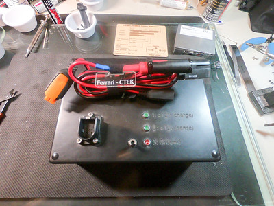
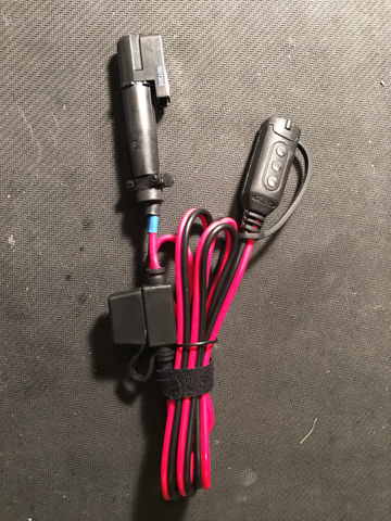
    For a number of years I’ve been making adaptor cables to convert from the proprietary Ferrari charger connector to the CTEK connector. This allows people to use the CTEK series of chargers to charge / battery tend their Ferraris. Ferrari rebrands the (lowest end) CTEK, and puts on thier proprietary connector, but many people would rather use one of the higher end / more sophisticated CTEK, or replace a dead Ferrari branded one, etc. 

    Using the Ferrari connector is much nicer than simply wiring the ring terminals to the battery, including:

    • It is more convenient – the Ferrari connector is bolted to the vehicle, and so less fiddling around in the footwell.
    • Much simpler – you simply plug in a connector, you don’t have to unbolt panels and bolt ring terminals to the battery.
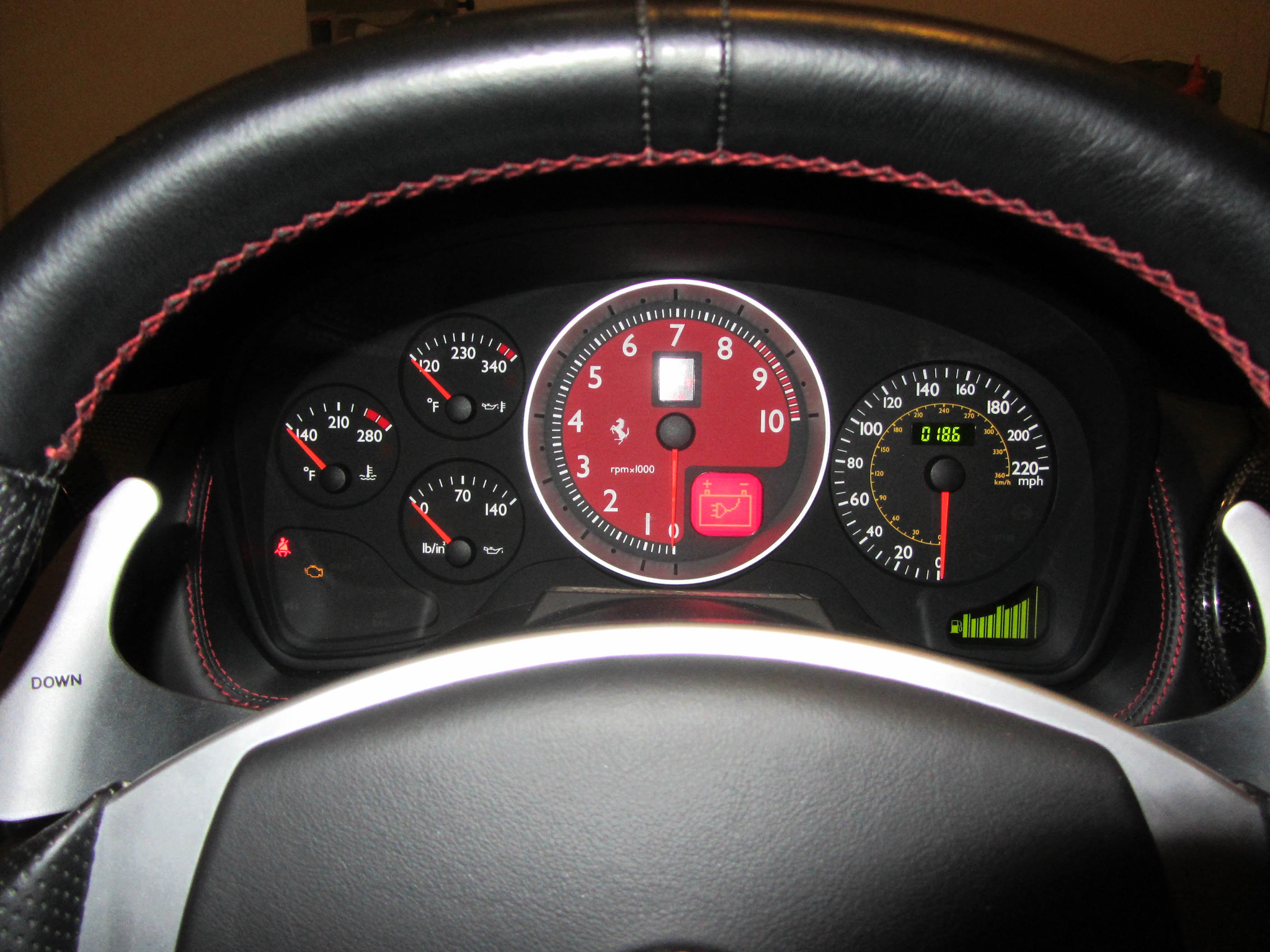
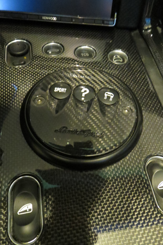
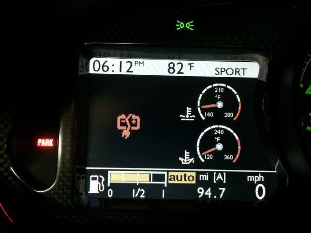
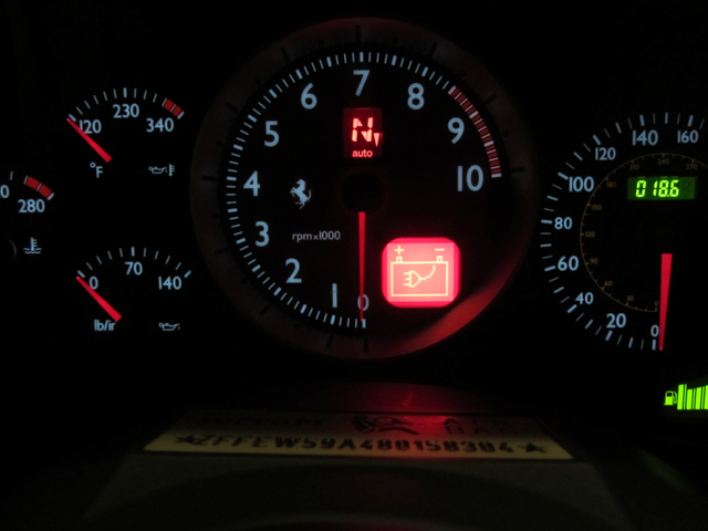
    • Most importantly (to me at least), the Ferrari connector includes a “sense” wire. This means that the car will display an icon on the dashboard and refuse to start while the charger is connected, this prevents the embarrassing driving off while the charger is connected issue 🙂

    599GTB Charger connected  F430 charger connected

    I make (and see these) cables, but I’m as happy for people to make their own (I’m somewhat OCD about making cables, and have over-engineered these. This means that it takes me around an hour per cable to make. The amount I sell them for isn’t really worth my time, so I mostly make these for the good of the community).

    If you have any questions, email me at warren@kumari.net.


    Parts:

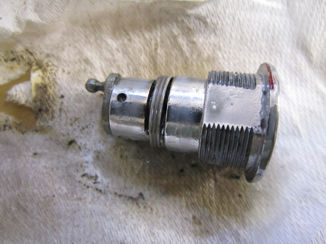
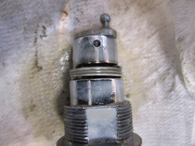
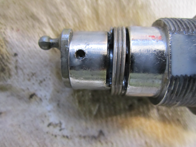
    • MBG4P-1 – DigiKey: SOU1192-ND $8.05ea – 4 Pin Souriau MBG Series Connector
    • MBG4S-1 – DigiKey: SOU1196-ND $4.30ea – 4 Pin Souriau MBG Series Shell / Strain Relief.
    • RC14M50K – DigiKey: SOU1970-ND $1.11ea (x 3) – Souriau 14AWG Machined Crimp Connector OR
    • SC14ML1S6 – DigiKey: SOU1247-ND $1.62ea (x 3) –  Souriau 14AWG Stamped Crimp Connector
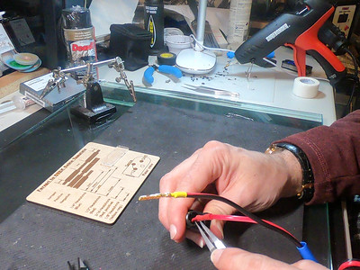
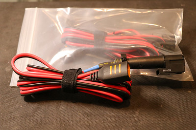
    • CTEK (56-384) – Amazon: LINK $9.99 – Comfort Indicator Clamps
    • 18AWG strunded wire
    • Various heatshrink
    • Hotglue

    I have provided part numbers for both machined (RC14M50K) and stamped (SC14ML1S6) contacts. The machined contacts are much nicer, but require a specific crimper head (S16RCM1450  $292) and handles (SHANDLES $125). The stamped ones work OK, and I’m using them in this tutorial because I don’t really expect people to buy $417 worth of crimper just to build one cable. Actually, I’m using the stamped connectors meyelf at the moment, because my S16RCM1450 head broke, and the replacement is backordered till 1/8/2016. Whatever contacts you choose, you should buy a bunch of them – Digikey shipping is quite expensive, and you may miscrimp some.
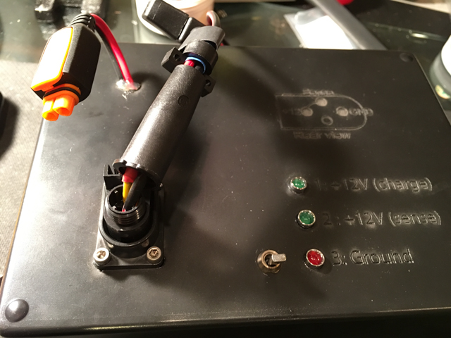
    Pinout:

    • Pin 1: +12V
    • Pin 2: Sense
    • Pin 3: Ground
    • Pin 4: N/C

    When Pin2 is raised to +12V to illuminate the warning icon on the instrument panel and prevent the vehicle from starting.

    Instructions:

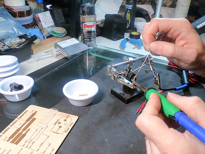
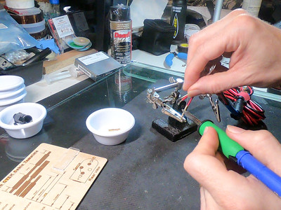
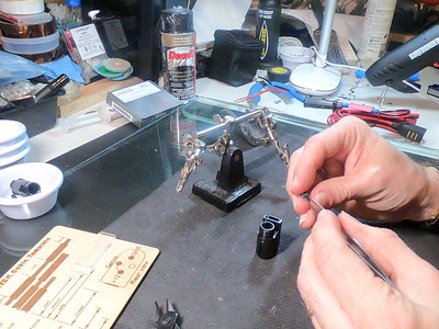
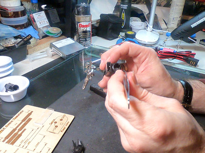
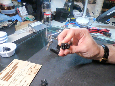
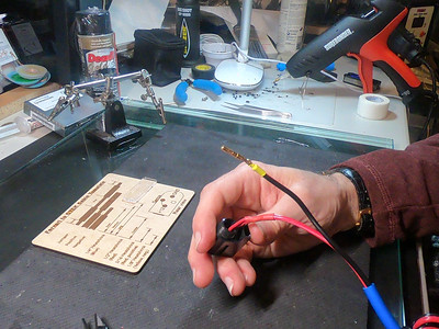
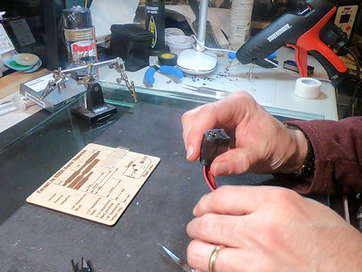
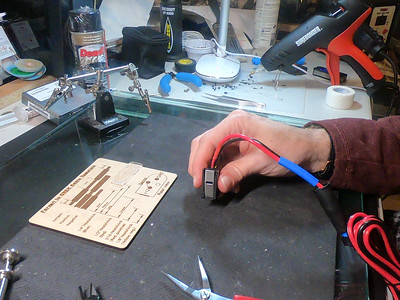
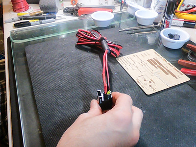
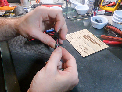
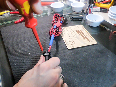
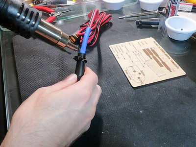
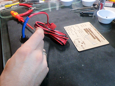
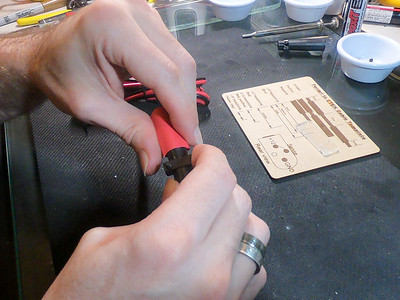
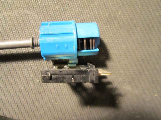
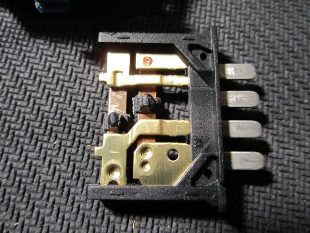
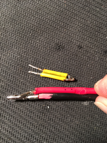
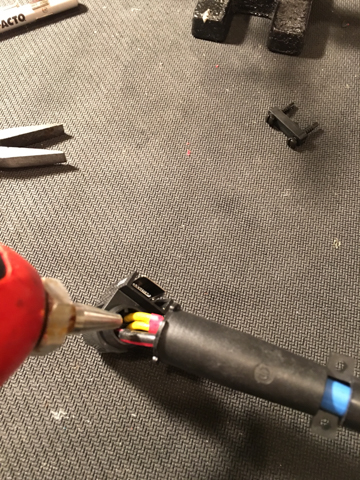
    Start off by removing the clamp connectors – prise off the plastic protectors, and then unsolder the clamps. Do not cut off the clamps, or the remaining wire will be too short to easily insert with the strain relief and connector.

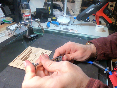
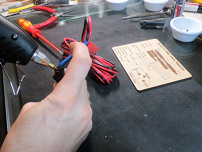
    Crimp a contact onto the (tinned) black (ground) wire. As I mentioned, I’m a little anal about making cables, and so I go a little overboard. This is how I do mine:

    IMG 3007

    Add a tiny bit of flux into the connector cup, and then add some solder into the cup. Then put in the tinned cable, and heat if from the bottom (to make sure that solder fully wets / flows. Then crimp (with good quality, ratcheting crimper with the correct sized head, for example a Wiha 436) the connector on, and finally flux over the top of the crimp and solder over the top. I’ve tested this system, and it provides me a much stronger (and lower resistance) connection than crimping or soldering by itself.

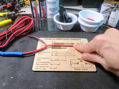
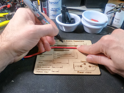
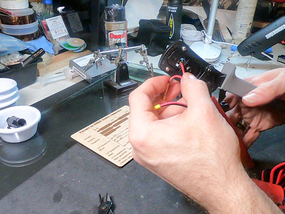
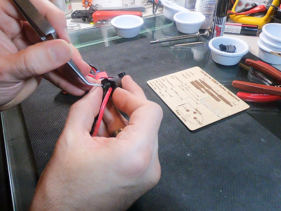
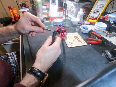
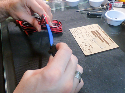
    Next, cut a 3.5″ piece of 16AWG stranded wire. Fold this in half, and mark 0.25″ down from the fold. Unfold this, score round the insulation and then cut down the length of the insulation, and remove this piece. Then trim ~0.25″ of insulation from each end.

    IMG 3023  IMG 3024  IMG 3025

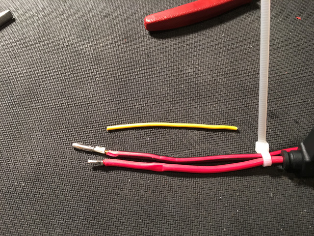
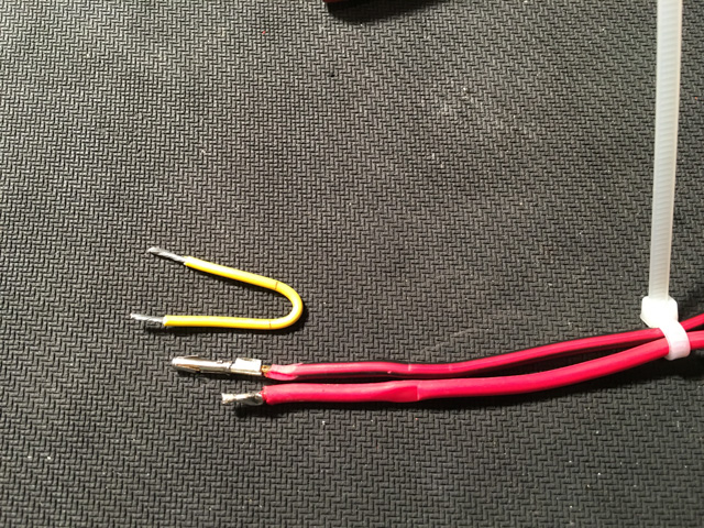
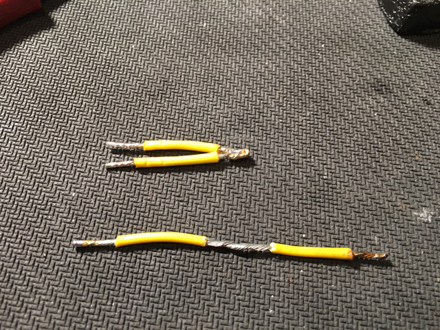
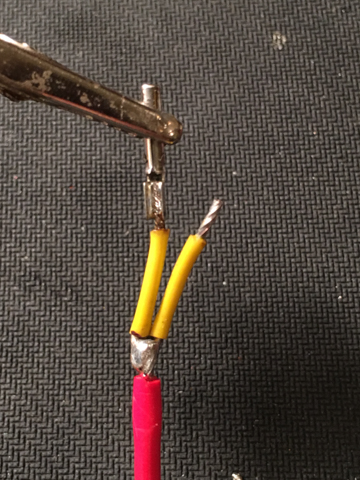
    Now, fold the cable again, liberally flux it and then tin the center and ends. Make sure to not have the insulation touching when tinning the center or it will stick. Now, lay the folded, tinned 16AWG wire next to the carger cable, and carefully align them. I ziptie the red and black together to make sure that they are nicely aligned. Now, mark and cut the red (12V) cable, making sure to take into account the length of the wire going into the contacts, and enough to solder – you want the wires to be the same length so that they have the same tension. Solder the contacts onto the ends of the 16AWG wire, using the technique above. 

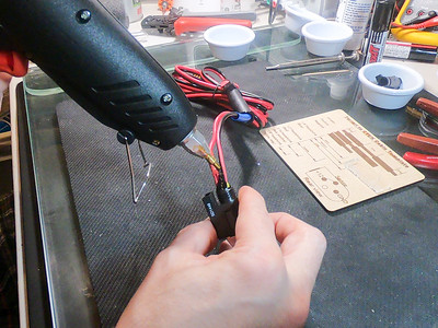
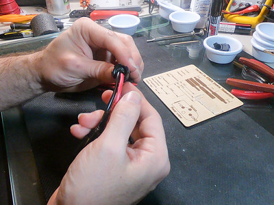
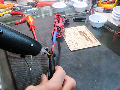
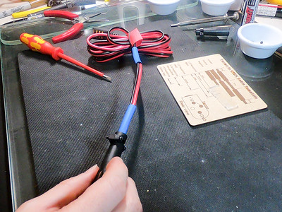
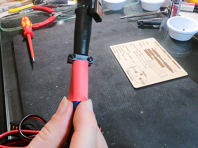
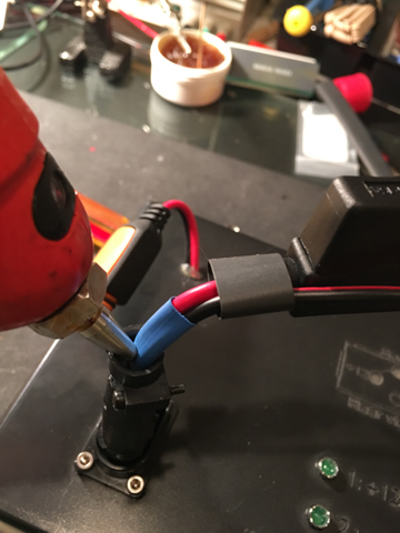
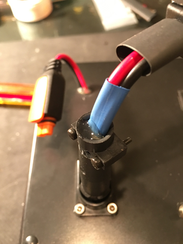
    Now solder the charger wire onto the 16AWG jumper, and put on a bit of heatshrink.

    IMG 3006  IMG 3007 IMG 3028  IMG 3010

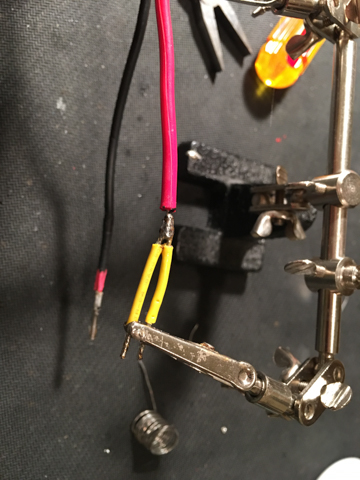
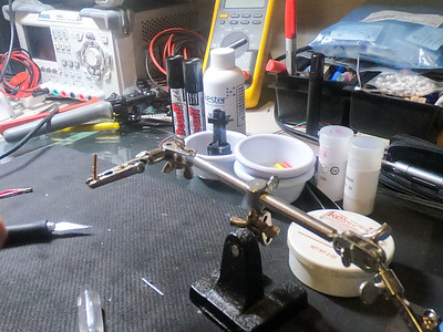
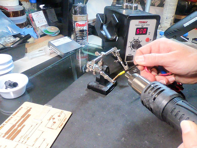
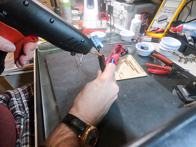
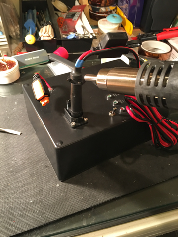
    When shrinking the heatshrink, I use a hot air surface mount solderer. This works much better than a heat gun (or lighter!), because it makes a much more focused stream of air – without this, you rish melting the insulation. 

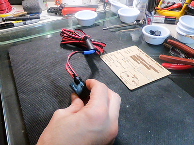
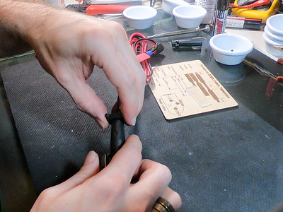
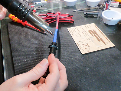
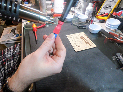
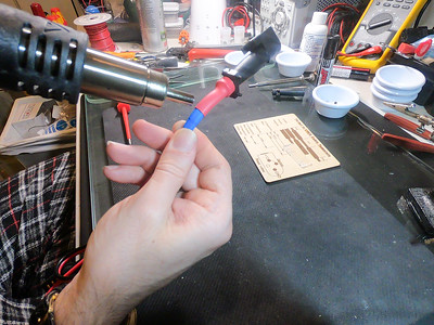
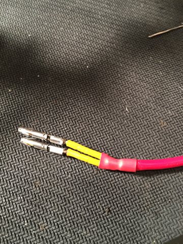
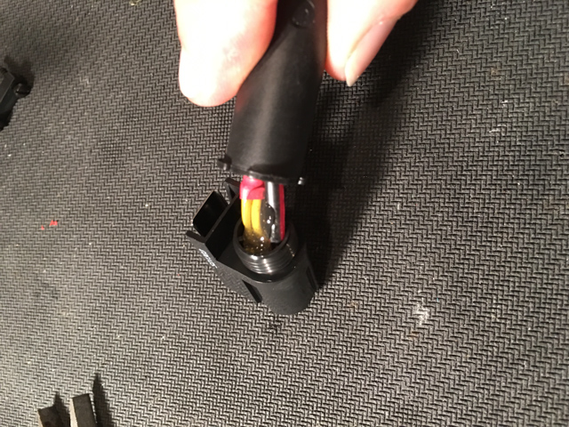
    Next, slide on some heatshrink and don’t forget the shield, or you will become very sad. 🙂

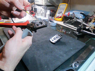
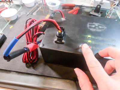
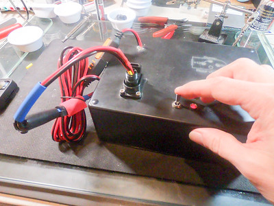
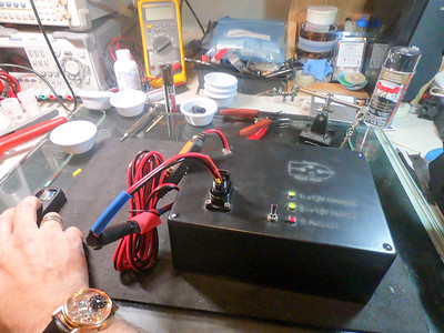
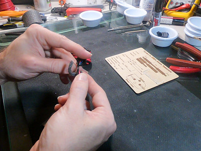
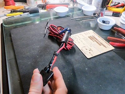
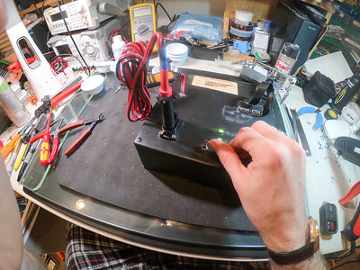
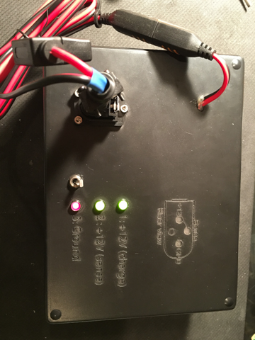
    Now, insert the contacts into the shell, making sure that the contacts have fully seated. This will be quite fiddly (especially if you included some heatshrink to go over the back of the strain relief), and you will be glad that you unsoldered the clamps, because this gives you an extra ~0.25″. I use a pair of needle nosed pliars to push the wires from the back. Now, test the pinouts to make sure you have it all right. I have built a test jig to allow me to accuratly and quickly test mine, but a multimeter will work. 

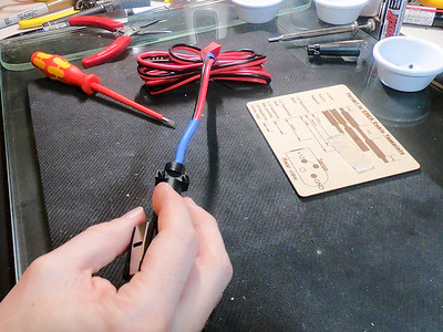
    Once you have triple checked the pinouts and that there are no shorts, squeeze some hotglue into the back of the connector shell, slightly overfilling it, and then quickly screw the strain relief on. This will tightly hold the cables, provide good strain releif, help keep things dry (and corrosion free), and prevent it unscrewing.

    IMG 3012  IMG 3026 IMG 3027

    Now, add some more hotglue in through the cutout in the strain relief, and quickly screw the cable clamp onto the back. Some hotglue will squish out, trim this off with an xacto knife, and then hit it with a heatgun to clean it up. Now, put some more glue in through the back of the strain relief and slide the last piece of heat-shrink over the back and shrink it on.

    IMG 3015 IMG 3016 IMG 3017 

    Finally, test it one last time, and you are done!

    IMG 3019  IMG 3021

    You could do this all with much less work, by cutting a bunch of corners (like just crimping the contacts, or splicing wires together, or not using the correct crimper), but, if you are going to bother doing it at all, you might as well do it right.


  • LR Series IIA – Work spreadsheet

    Here is some of the work I’ve been doing on the Land Rover. 


  • Ferrari 308 Projects

    Ferrari 308 Projects

    P1030003

    I recently got a 1980 Ferrari 308GTSi, primarily as a restoration and project car.
    I first fell in love with Ferraris from watching Magnum P.I, and this is the Magnum car, so…

    I’ve put up some photos of the car here and some of the work photos here

    I’m planning on making sub-pages with details on some of the repairs for others.

    I’ve been trying to keep a list of what all I’ve done to it. I’ve managed to forget many of the things (many of them are a “while I’m in here I might as well just…” type events). Here is an initial list, from April 2014 to August 2014:

    What
    Changed drivers’s rear outside brake caliper.
    Bled brakes (drivers rear only, purchaced caliper adjuster covers)
    Installed Edelbrock/Russell Speed Bleeders on rear calibers
    Removed handbrake pully mechanism, disassembled, cleaned and lubed
    Painted rear emblems.
    Removed driver’s door panel, lubricated the window motor / mechanism, cleaned window switch contacts.
    Cleaned signal / headlight contacts.
    Removed driver’s seat, fixed seat rails (slider mechanism / bearing worn, removed bearings)
    Removed and clean shift knob, removed and polished shift gate.
    Removed tail lights, disassembled and cleaned
    Installed JVC KD-NX5000 Single DIN NAV system
    Installed replacement powered radio antenna
    Removed and cleaned battery connectors, grounds in front trunk, repaied battery cutoff switch.
    Made new spare wheel tie down (McMaster Carr)
    Installed Dynamat in trunk, cleaned and repaied sound insulation / heat stuff
    Reglued trunk carpets (rear, light covers, etc)
    Redid the trunk weather stripping (replace sometime?)
    Painted exhaust / cat cover
    Removed and painted pedals
    Disconnected cold start air valve
    Cleaned contacts on Magneti Marelli MED 801A Digiplex (ECUs)
    Cleaned contacts on ignition coils
    Installed new fuel accumulator. Discovered frayed fuel hose.
    Installed new LED headlights
    Installed new braided steel tank to pump fuel line
    Replaced clock.
    Removed and painted plenum
    Removed and cleaned throttle body
    Replaced fuel lines from fuel distributor to the injectors on bank 1
    Replaced all fuel injectors – reused injector seals
    Replaced the oil sender unit.
    Replaced oil filter / oil / crush washer
    Replaced fuel lines from fuel distributor to the injectors on bank 2
    Drove Bluemont to Dulles
    Drove Father’s Day carshow.
    Fixed fiberglass in passender door card (so card stays on better)
    Installed Dynamat in passenger door card
    Restrung and relubricated the passenger side window. Now closes fully!
    Installed new door edge warning lights
    Adjusted passenger door lock / locking mechanism
    Installed stainless steel braided brake lines, bled brakes.
    Installed new front and rear brake pads
    Painted and reinstalled undertray
    Adjusted handbrake cable
    Replaced fuel filler hose (Gates 23976), cleaned up filler neck, cap, vent tubes
    Cleaned and painted passenger fron suspension arms
    Created battery tie down plate, bolted down battery.
    Installed new battery cut-off switch
    Adjusted clutch cable, took up slack and lubricated cable (now doesn’t have odd detent!)
    Installed new duct to airbox boot.
    Installed Verell’s shifter bushing
    Repaired driver’s door lock spring.


    P1030007

    P1030013

  • Ferrari 308 Door lock spring

    Ferrari 308 Door lock spring

    Recently I discovered an issue with my driver’s side door lock. I almost never use it, because I usualy do not have the targa top on, and so thier is no point on locking the door – anyone can just reach in over the window and pull up on the door locking knob. 

    Anyway, while repairing the slow window issue on the passenger side (required restringing the entire window) I decided to lubricate the lock, and so when I replaced the door edge lamp on the driver’s side I figured I should do the same. At this point I noticed that the driver’s side lock does not return to center when turning the key – this means that you have to fiddle with the key to get the lock to stay down, and be able to remove the key. 

    Anyway, I decided that this would drive me nuts, so I removed the door card (yet again!) and then unbolted the door lock (below picture of passenger side, forgot to take driver side photo)

    IMG 0557

    When I removed the lock I found the issue. There is a return spring that wraps around the lock assembly, and the ends of the spring stick through the shell into the plug. When the plug is rotated from center, either one side or the other of the return spring gets engadged, trying to pull it back to center. One arm of the return sptring had sheared off, right at the bend.

    To repair it I first cleaned off all the old, accumulated grease with brake cleaner and then slid the return spring out of the slot and off the end of the barrel. I then bent a new arm (of about 5.5mm) in the spring right where it had sheared. I then slid it back over the barell, and engadged each end of the spring. Beacuse the spring is very slightly shorter (around 10mm) it is probably very slightly harder to turn, but this is not in any way noticialbe (and the spring has probably lost some of it’s tension over time, so this cancels out :-))

    I then sprayed the keyway with dry lube, and the whole body with spray lithium. A small bit of RTV silocone goes on the head / barrel nut to try keep it all waterproof, and done!


    Some photos of the repaired lock:

    IMG 0585IMG 0586

    IMG 0587

  • Murcielago Push Button Start

    Murcielago Push Button Start

    Adding push button start to a Lamborghini Murcielago.

    The Murcielgo uses the same center console switch unit as the Gallardo, but only two of the three buttons do anything – the third simply sits there, taunting me. I really wanted the center switch to do something… anything… So, while she was put way for the winter, I decided to make the unused center button into an Engine Start / Stop button.


    This is some info on the project.

    IMG 0187IMG 0185
    Center switches.

    Having a big “?” on the center switch helped with the annoyance somewhat. For a while I considered replacing the (hand painted) “?” with “Ejector Seat”, but wanted it to actually do something, so…

     IMG 0188IMG 0189

    Center switch unit

    IMG 0190IMG 0191

    IMG 0192Marked up center switch
    Disassembled center switch unit. Marked up with components.


    As you can see from the final picture, the center switch unit is missing the center switch itself. I was hoping to be able to read the manufacturer and part number off one of the other switches without removing them from the baord, but no such luck, so I unsoldered the rightmost one, and… was still not able to find a manufacturer… After spending a large amount of time looking through online catalogs at DigiKey and Mouser and similar I finally found the correct switch at Jameco Electronics.
    They are Omron B3E-1100-GREEN (or B3E-1100-RED), Jameco part number 2076287, available here. The board is also missing a surface mount green LEDs and two 470Ω SMT resistors for illumination. I had a bunch of LEDs around, but had run low on SMT resistors so I ordered some more as well. When I went to install them I discovered that the LEDs I had were 0603 package (and not 1206), but with a bit of careful soldering was able to make them reach.

    IMG 0201IMG 0202
    Soldered on switch, LEDs.

    I was originally planning on having the middle button only perform the “crank” function (engage the starter motor); this would have been really simple, just hook the switch up to a relay and run wires to the back of the keylock unit… But, once I’d gotten this far into the project I decided I might as well go all the way and have the single button perform all the actions.

    As there is only one button I had to get a bit creative with the interface. The first press of the button turns on Accessory (ACC) mode. The next press turns on Ignition (IGN). A third press turns everything off again. While Ignition is on, pressing and holding the button for more than one second cranks the motor. To keep things simple (and make it easier if anyone else wants to do this) I decided to do this with an Arduino.

    IMG 0207IMG 0205
    Prototype Arduino (extra LEDs for debugging) and relay board

    I did the prototyping on a breadboard with a Boarduino (Arduino compatible) Kit w/ATmega328 from one of my favorite online places, Adafruit Indutries. There is no way that the Arduino will be able to switch the required current, so I built a little relay board with two relays, each with a snubber diode and a transistor to switch it. The only relays I had in stock were either quite small (like above) or really large, and needing 48v for the coil. I settled on the small ones, but their contacts are only rated for 2A @ 30V. After wasting an hour or so with this I looked online and found Amazon selling SainSmart 4-Channel Relay Modules for <$14 Prime. These have 4 relays rated at AC250V 10A, DC30V 10A, opto-isolators, indicator LEDs, etc and are designed to be driven by a microcontroller. I decided to just order these (and a bunch more for keeping in stock :-)) and play with the code instead.


    [ MORE TO COME, Including Arduino source, relay info, STL for the buttons themselves, steering switch lock, etc. ]


  • Lamborghini Murciélago e-gear issues

    Lamborghini Murciélago e-gear issues

    I recently started having really weird e-gear issues in my Murciélago Roadster.

    The first sign of problems was when I stopped in a parking lot, left it in 1st and went into a grocery store. When I came out, it refused to start, or come out of gear. I called Josh at ECS and we tried hooking it up to a Leonardo, which showed correct hydraulic pressure, but it simply refused to change gear. I ended up having to put it on a flatbed, but, because it was stuck in gear (and is all wheel drive) this was difficult. We ended up having to raise it on wheel jacks and winch it onto the flatbed.

    When it got to the shop it misbehaved for a while – we added some hydraulic fluid, and bled the system, and then suddenly it started working. While doing this, Josh also adjusted the P.I.S (Point of Initial Slippage) – this made the shifts much much smoother.

    A few weeks later I was just turning back into my driveway, and it started behaving oddly again – she didn’t really seem to want to change gears, but grudgingly agreed to after a few pulls on the paddles… but it all felt “weird”. I put it in the garage and called Josh.

    He made a house call and we spent some time with the computer, exercising the E-gear actuator. It kept working properly, which was very frustrating – I didn’t want to be driving the vehicle not knowing what the issue was, or when it might happen again… and then, suddenly, it all stopped. Instructing it to change gears, either through the paddles, or through the computer resulted in her simply ignoring us.

    We then noticed that she had just logged a brake switch error…

    When I first purchased the Murciélago I spent a bunch of time reading up on known issues. The main one that people were mentioning was the fact that the brake switch was a known weak point, and would suddenly die and leave the owner stranded. I purchased a spare brake switch, “just in case” and kept it in the trunk (this was the one and only emergency spare part I got). We tested that this was a problem by watching the brake sensor output in the computer – sometimes it would believe that the brake pedal was pushed when it wasn’t, sometimes it would believe that the pedal was not pushed when it was.

    Removing the old brake switch is easy – you climb into the driver’s footwell, the brake switch is mounted on a bracket facing the brake lever. You remove the electrical connector, and then rotate the switch to remove it. 

    IMG 0530 IMG 0531IMG 0532

    Replacing the switch is significantly harder, at least until you know the tricks. The problem is that the front of the switch needs to go through the keyway in the bracket, and then rotate to lock in into place. There is an interlock that prevents the switch from rotating until the plunger is pressed and held in. After removing the  old switch, you might want to play with it to see how it locks, and how it turns.

    Installing it is made tricky by the fact that you are lying on your back in the footwell, and need one hand to press in the brake pedal to move it out of the way. You need your other hand to press the switch in, and then your third hand to press the plunger. If you happen to not have been born with only two hands, you are kind of stuck at this point. The trick which I finally figured out was to start the engine. This provides vacuum assist, and allows you to move the pedal with your hand (or by resting your head on the pedal) and install the switch with only 2 hands  

    This completely fixed the issue – we tested it on the Leonardo for a while, and I’ve taken her out for a number of great drives, all with perfect, crisp shifts.

    I ended up disassembling the old switch to see how it worked, and more importantly, how it failed.

    IMG 0533 IMG 0536 IMG 0539 IMG 0538


    These show the disassembled brake switch. The pedal lever presses on the pin, which makes the blue plunger slide back. This slides over some cams, opening the contacts. It seems that, over time, the plunger wears down the plastic cams on the switch, leading to the contacts not fully opening / becoming intermittent. There are two sets of contacts, it sems that one is actually for detecting when the switch is pressed, and the second is a self test / monitoring pair. This all seems way over engineered.

    Replacement switches are really cheap (around $12.00USD), and, in my opinion, worth keeping one in the car, just in case it fails while you are out on the road.

    They are an Audi part (3B0945511C, these superceed 3B0945511B), and are used in various cars, including Lamborghini Murciélago, Gallardo Spyders, Superleggera, Audi A4, A5, A6 and VW Golf mk5.

    Ricambi America has them here and BullStuff has them here.


  • Aston Martin V8 Vantage

    Aston Martin V8 Vantage

    A while back I replaced the stock muffler on my Aston Martin with a QuickSilver SuperSports-Plus system. This is much lighter (24lb vs 40lb) than the stock unit, and has a great sound.


    This completely changed the entire feel of the car, and took if from being a sedate grand tourer to a proper sports car that loves twisty backroads. As far as I’m concerned this is one of the best exhaust notes I’ve ever heard (other than maybe the Murcielago with a custom exhaust in a tunnel), way more musical than the typical Ferrari note.

    Replacing the muffler required removing all the under trays. I took this opportunity to clear / polish the trays, check the air filters (which were remarkably clean), etc.

    The hardest part (other then the really heavy old muffler) was finding the donut exhaust gaskets. It seems that basically no-one other than the dealer stocks these. A temporary alternative is to take two half-donuts and slather them with muffler and exhaust sealant and use these — at least until the dealer gets the right ones in stock.


    More photos here